


Sanitary Safety Relief Valve with Pressure Gauge
This high-performance sanitary safety relief valve with an integrated pressure gauge is engineered to protect pipelines, tanks, pumps, and other hygienic processing equipment from overpressure risks. The built-in pressure gauge provides real-time, direct pressure monitoring, enabling precise pressure control and process traceability. Constructed from premium stainless steel with a fully hygienic design, it meets the strict hygiene and safety standards of the food, beverage, pharmaceutical, and fine chemical industries, offering reliable pressure relief and clear pressure feedback for critical processes.
| Parameter | Details |
|---|---|
| Size Range | 1/2″ – 4″; DN15 – DN100 |
| Kv Value | 8.5 – 180 m³/h |
| Max. Working Temperature | 150℃ |
| Adjustable Pressure Range | 0-0.3 MPa; 0-0.6 MPa; 0.6-1.0 MPa |
| Body Material | Stainless Steel 304 / 316L |
| Applicable Media | Air, Steam, Water, Liquid, Gas |
| Connection Type | Sanitary Clamp, Thread, Welding, Flange |
| Gauge Features | Built-in, color-coded pressure gauge for real-time monitoring |
Sanitary Safety Relief Valve with Pressure Gauge
Key Features
- Integrated Pressure Gauge: Equipped with a clear, color-coded pressure gauge for direct, real-time monitoring of line pressure, eliminating the need for additional pressure measurement points and enabling quick, accurate pressure adjustment.
- Precise Overpressure Protection: The spring-loaded mechanism maintains a tight seal under normal operating conditions, automatically opening to relieve excess pressure when the set threshold is reached, preventing equipment damage and safety hazards.
- Hygienic, Dead-Space-Free Construction: Manufactured from 304/316L stainless steel with smooth, polished surfaces and crevice-free design, fully compatible with CIP/SIP cleaning processes to meet strict sanitary requirements.
- Adjustable Set Pressure: The pressure can be easily calibrated via the top adjustment knob, offering flexible adaptability to different process pressure requirements.
- Sanitary Connection Options: Available in sanitary clamp, thread, welding, or flange connections for seamless integration into various hygienic pipeline systems.
Technical Specifications
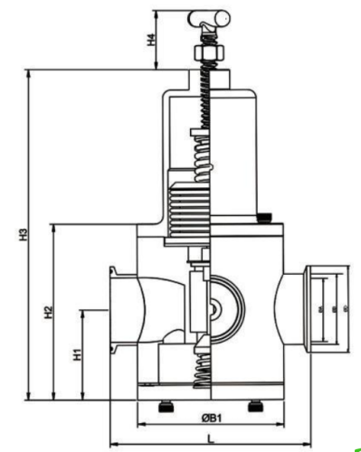
| Size | A | B | D | B1 | L | H1 | H2 | H3 | H4 |
| 3/4″ | 16 | 19 | 25 | 88 | 139 | 56 | 109 | 215 | 80.5 |
| 3/4″ | 16 | 19 | 50.5 | 88 | 139 | 56 | 109 | 215 | 80.5 |
| 1″ | 22 | 25 | 50.5 | 88 | 139 | 56 | 109 | 215 | 80.5 |
| 1-1/4″ | 28.5 | 32 | 50.5 | 88 | 133 | 56 | 109 | 215 | 80.5 |
| 1-1/2″ | 35 | 38 | 50.5 | 88 | 133 | 56 | 109 | 215 | 80.5 |
| 2″ | 47.5 | 51 | 64 | 108 | 148 | 65 | 129 | 243.5 | 80.5 |
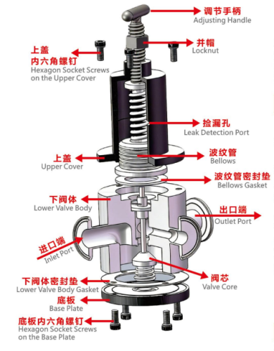
- Attention shall be paid to the inlet direction of the pressure reducing valve during installation; install it correctly in accordance with the inlet and outlet direction indicated by the arrow on the valve body.
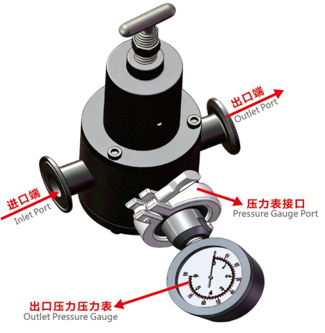
- Pressure Adjustment Method for the Pressure Reducing Valve: Unscrew the locknut, rotate the adjusting handle clockwise to increase the outlet pressure or counterclockwise to decrease the outlet pressure. The pressure gauge on the valve body displays the outlet pressure. Observe the value change of the pressure gauge, rotate the adjusting handle slowly to the required pressure value, then tighten the locknut to complete the pressure adjustment.
Troubleshooting instruction
No Pressure Reduction
①The outlet end of the pressure reducing valve has no pressure, and the reading on the pressure gauge of the valve body is zero. Follow the pressure adjustment procedure for the pressure reducing valve.
②The reading on the pressure gauge of the pressure reducing valve is consistent with the inlet pressure. Check if the valve is installed in the correct direction. If the installation direction is correct, follow the pressure adjustment procedure for the pressure reducing valve. If the problem persists, the valve core may be damaged and needs replacement.
③Air or water leakage from the leak detection port: The bellows is damaged and needs replacement.
④Air or water leakage from the gap between the upper cover and the lower valve body: Tighten the hexagon socket screws on the upper cover. If the problem cannot be resolved, replace the bellows gasket.
⑤Air or water leakage from the gap between the base plate and the lower valve body: Tighten the hexagon socket screws on the base plate. If the problem cannot be resolved, replace the lower valve body gasket.
Application:
- Food & Beverage: Dairy processing, beverage production, brewing, and food manufacturing lines
- Pharmaceutical & Biotech: Drug manufacturing, sterile processing, and biopharmaceutical production
- Fine Chemicals: Cosmetics, personal care products, and hygienic chemical processing
- Other Industries: Water treatment systems, steam distribution networks, and industrial processes requiring sanitary pressure relief with pressure feedback


