

Pressure Balance Thermostatic Steam Trap TC-C
Designed for condensate drainage in clean steam systems. It is suitable for reactors, sterilizers, process vessels, CIP/SIP systems and branch pipes of clean steam systems. The valve body has a high surface finish with an internal polishing degree of 0.6μm. Its self-draining design and true anti-condensation design minimize condensate water accumulation and the risk of “water hammer”. The “fail-open” design ensures no condensate water accumulation in the steam space.
The large opening valve disc enables rapid air discharge, quick start-up, clog prevention and continuous operation. It features a compact structure, easy installation and maintenance, low maintenance costs. Optional internal electropolishing (cost not included) to a Ra value of 0.2-0.4μm and external polishing to 0.6μm is available for further prevention of bacterial growth.
‘•Model No.: TC-C
•Connection type: Tri Clamp
•Specification: 1/2″ to 1-1/2″
•Nominal pressure: 1.0Mpa
•Max pressure: 0.8Mpa
•Max pressure difference: 0.6Mpa
•Max temperature: 180℃
Pressure Balance Thermostatic Steam Trap TC-C
Key Features
- Sanitary Design for Clean Steam Systems
- 316L stainless steel body, polished to Ra ≤ 0.8μm, suitable for food, pharmaceutical and CIP/SIP applications.
- Fail-Open Safety Mechanism
- Thermostatic bellows element ensures condensate discharge even if the trap fails, preventing waterlogging and system shutdown risks.
- Rapid Air & Condensate Removal
- Large orifice disc design enables fast air and condensate discharge, avoiding air binding and ensuring quick system startup.
- Durable & Versatile Performance
- Rated for 1.0 MPa, 0.6 MPa differential pressure, up to 180℃, with excellent corrosion and fatigue resistance.
- Easy Installation & Maintenance
- Standard sanitary clamp connection for quick assembly/disassembly; compact structure supports CIP/SIP cleaning.
- Cost-Effective Replaceable Parts
- Spare components (bellows, filter, gasket) are replaceable, reducing long-term maintenance costs.
Technical Specifications
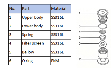
Material List
Size data
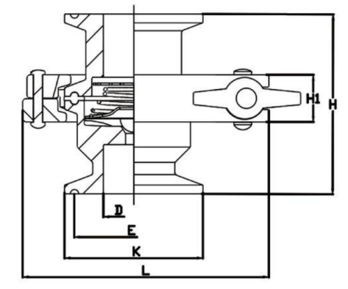
3A Standard
| Size | OD | D | E | K | L | H1 | H |
| 1/2″ | 12.7 | 9.4 | 22 | 25.2 | 89 | 17.3 | 66 |
| 3/4″ | 19 | 15..7 | 22 | 25.2 | 89 | 17.3 | 66 |
| 3/4″ | 19 | 15.7 | 43.5 | 50.5 | 89 | 17.3 | 66 |
| 1″ | 25 | 22 | 43.5 | 50.5 | 89 | 17.3 | 66 |
| 1-1/4″ | 32 | 28.5 | 43.5 | 50.5 | 89 | 17.3 | 66 |
| 1-1/2″ | 38 | 34.8 | 43.5 | 50.5 | 89 | 17.3 | 66 |
DIN Standard
| Size | OD | D | E | K | L | H1 | H |
| DN10 | 12 | 9 | 27.5 | 34 | 89 | 17.3 | 66 |
| DN15 | 18 | 15 | 27.5 | 34 | 89 | 17.3 | 66 |
| DN20 | 22 | 19 | 27.5 | 34 | 89 | 17.3 | 66 |
| DN25 | 28 | 58 | 43.5 | 50.5 | 89 | 17.3 | 66 |
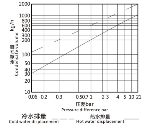
Displacement
Installation instruction
This steam trap shall be installed vertically with the liquid pocket kept horizontal and the inlet located at the top. For horizontal installation, install the trap horizontally with the liquid pocket kept horizontal. Install appropriate stop valves on both sides of the trap to ensure safety during maintenance or replacement. After installing, slowly unwrap the packaging parts and open the stop valve slowly until the system operates stably, and check for leaks.
Notes:


